Photos
various photos for other posts.
Corgitronics
various photos for other posts.
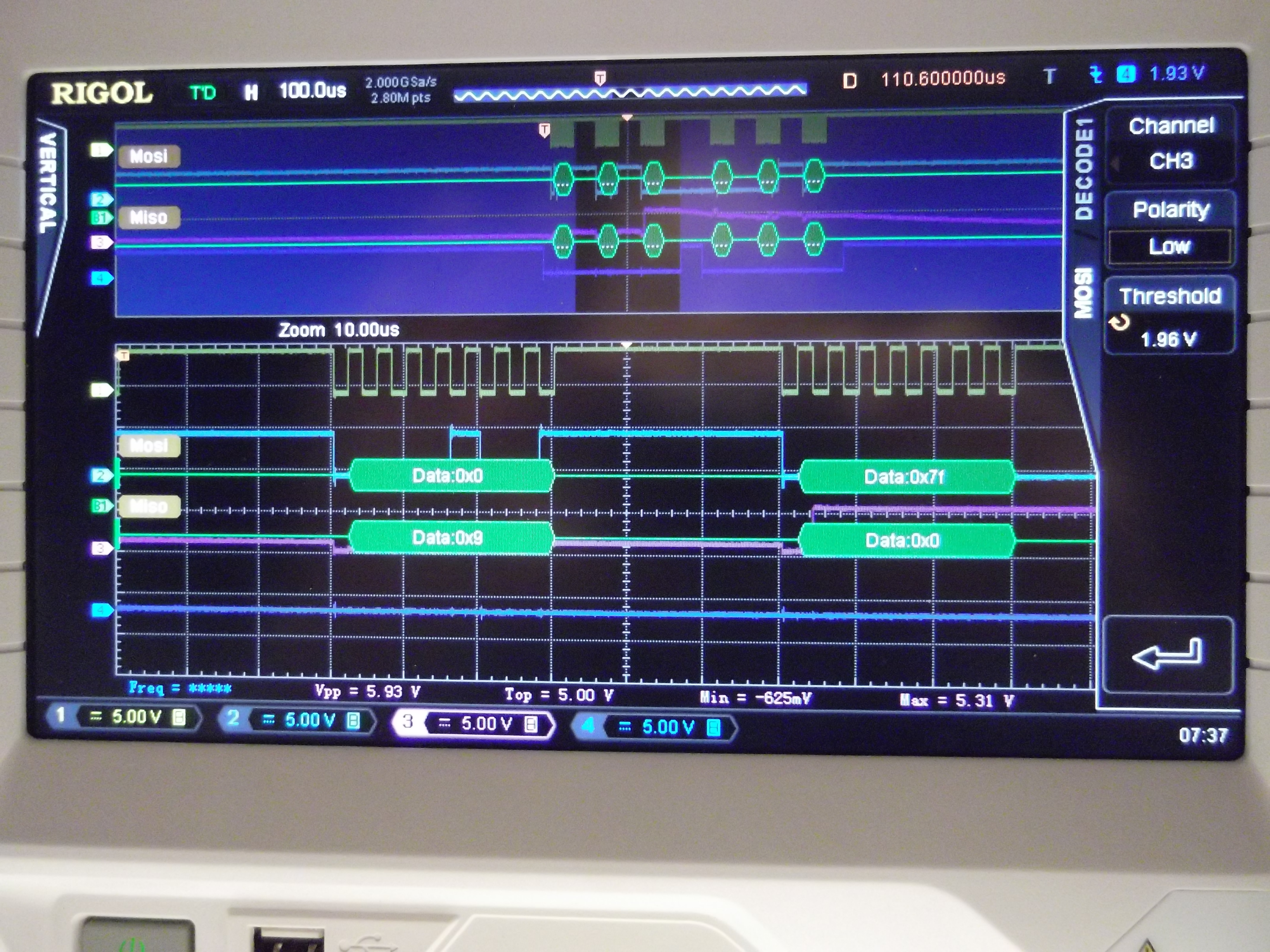
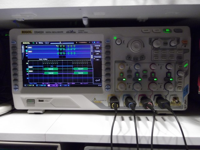
Tried out the SPI decoding capabilities of my new DS4024.
Very nice! It took a little playing around to figure out the settings. Since SPI isn’t completely standard, you need to make sure that the high/low option is correctly configured for each channel.
The picture doesn’t really do justice to the crisp image on the screen. Click the image below to zoom in for a clearer view. The screen is non-glare, but the camera seems to pick some up (more than I can see).
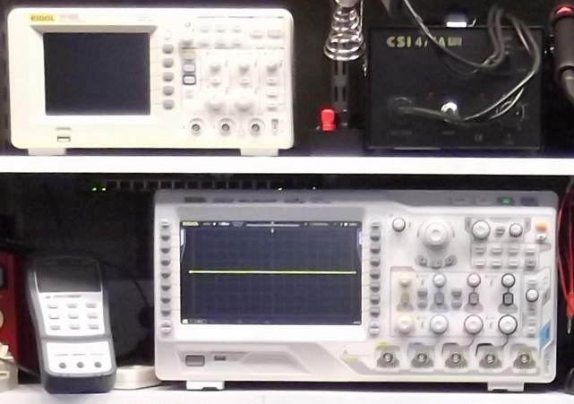
The DS4000 series oscilloscopes are big. Compare the 4000 to the DS1052E on the shelf above it.
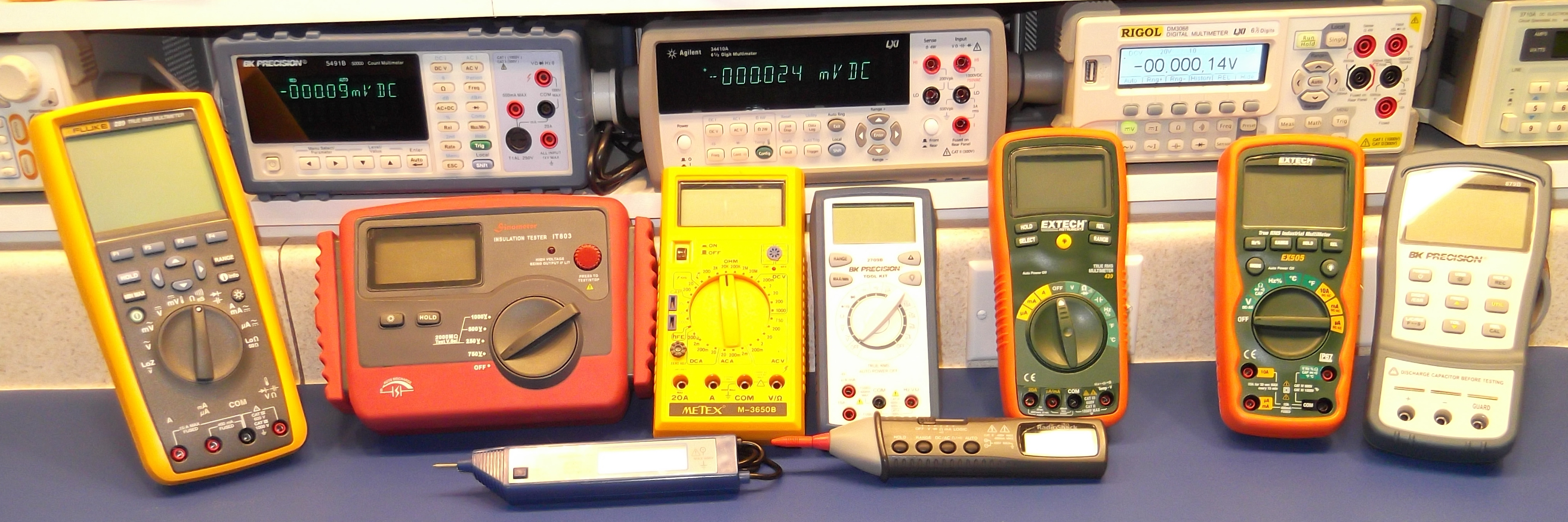
Various meters over the years. The probe type meters sound more useful than they’ve really been.
Bench meters: BK 5491B, Agilent 34410A, Rigol DM3068
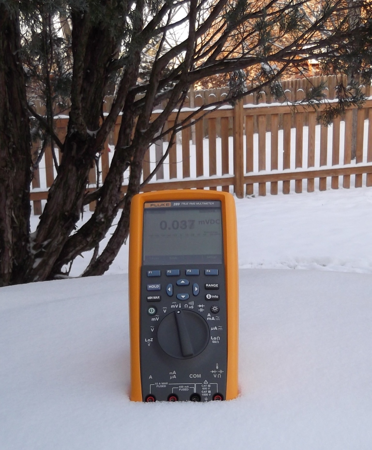
Hand held: Fluke 289, Sinometer IT803, my 23 year old Metex M-3650B, BK 2709B, Extech430 & 505, BK 879B
Bottom: A couple of probe meters
Yesterday, I received a small box of junk in priority mail.

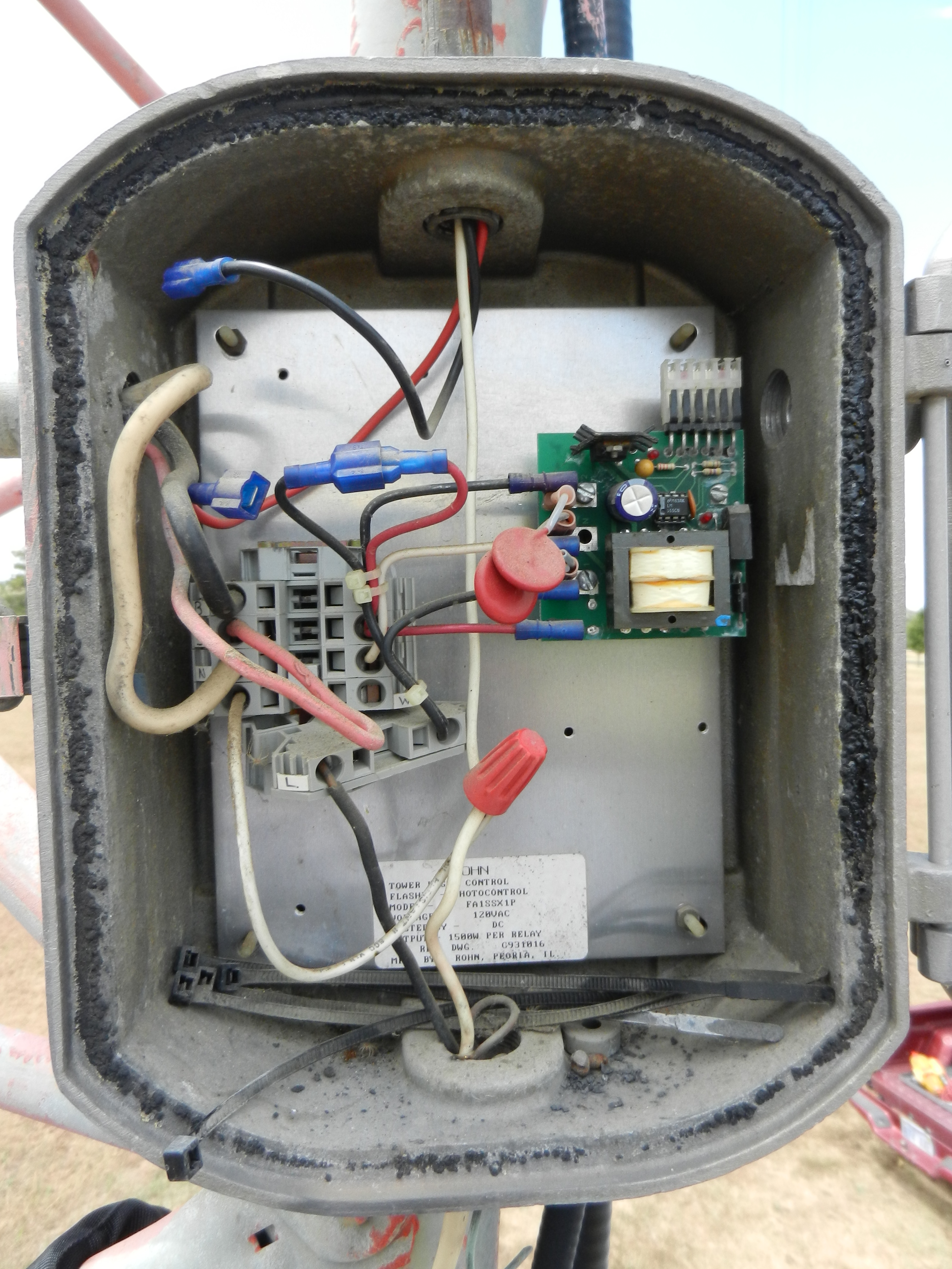
The lights weren’t working on a 400 ft. radio tower. The controller’s enclosure was damaged and water had gotten in.
The board had a fair amount of corrosion, and also some scorch marks.
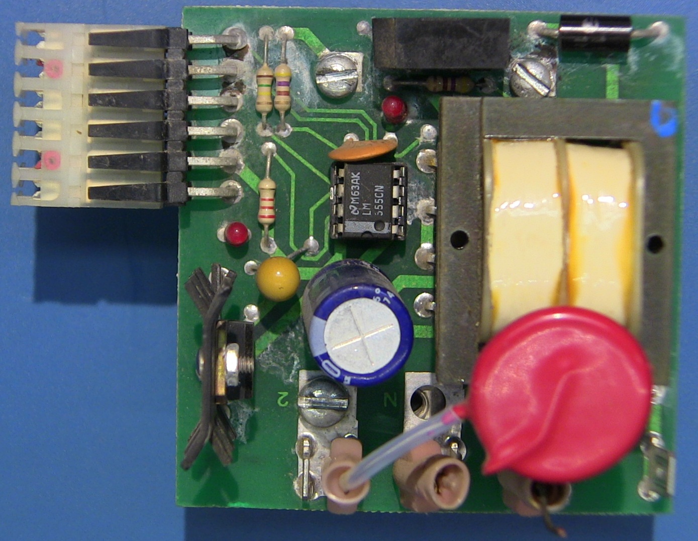
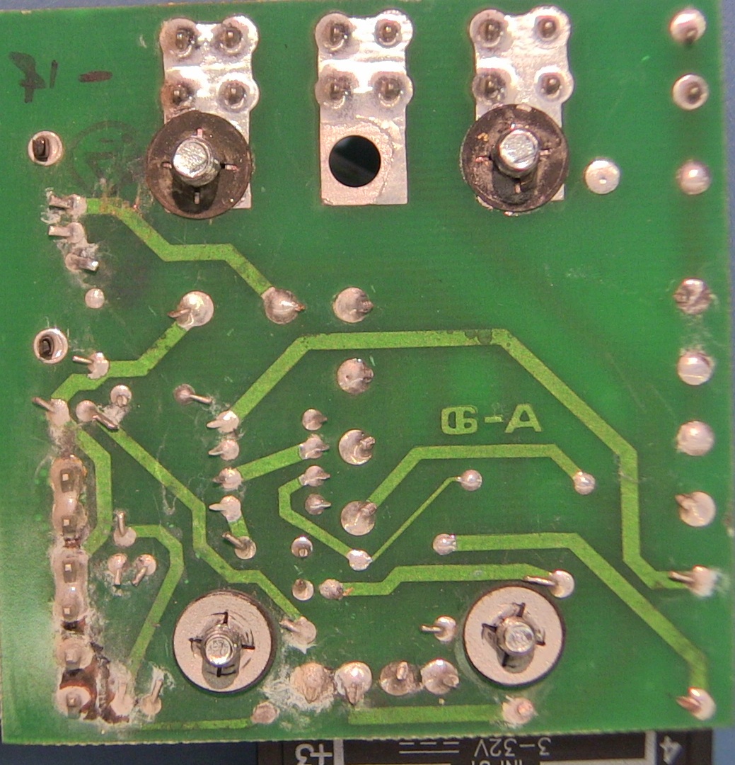
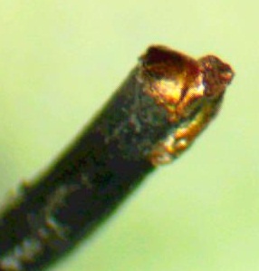
It looks like there may have been some transients from lightning, as the leads to one of the MOVs has melted.
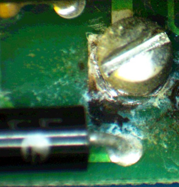
I toned out the connections, and it matches the typical NE555 oscillation circuit. The damage was mostly limited to the MOVs (150L20), and the TVS protection diode (1N6281C). But, before the TVS blew, it took out a couple of traces on the board. So,I just bodged in a couple of wires to repair the trace, and it’s all running again.
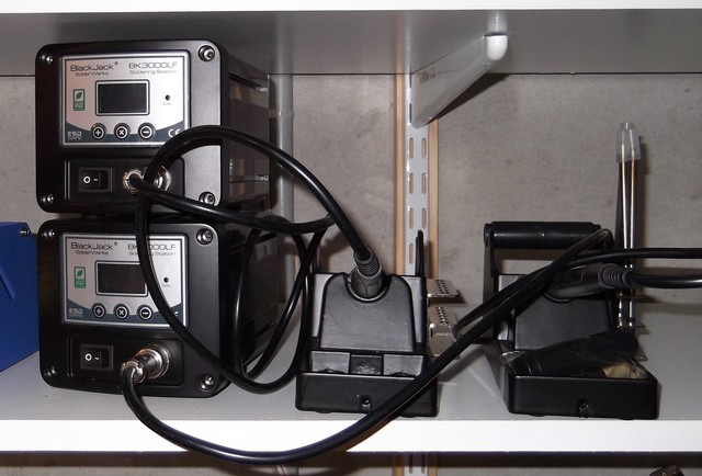
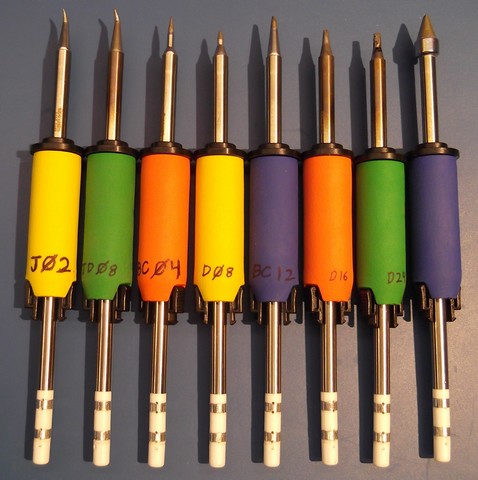
Last spring I had picked up a pair of BlackJack SolderWerks BK3000LF soldering stations with a couple of extra tips in different sizes. These have worked pretty well for the price (around $39 each at the time) and the control units stack conveniently to save space. But, they have trouble maintaining temperature when using desoldering braid… or even without using braid, they won’t really maintain temperatures above 360 C. Also, there aren’t any tips that work well for SMDs.
The price has gone up quite a bit in the past year, so I’d be a lot less inclined to get these now. The only place to get them, or any tips, appears to be from CircuitSpecialists.com. If they decide not to carry it, then I’m out of luck for parts.

So, I recently looked at the Hakko units. The FX-888 is a well made unit (see this hack at the eevBlog), even though it looks a bit like a toy. I also liked the FX-951, with the digital display. The 951 series is more of a professional unit, even though it too has the bright yellow and blue colors. There’s a huge selection of tips, and you can get extra snap-in grips which makes it easier to change the tips while they’re still a bit warm. The cables on the Hakko are thinner, more flexible, and a bit longer than on the BK-3000LF.
For most purposes, I’d generally go with the FX-888, it’s a great unit at a decent price. Hakko makes a variety of tips available from multiple sellers.
Why two soldering irons? I found that I often need two sizes during the same work session. When building a board I’ll use a small bent tip for surface mount devices, and a larger bevel tip for through-hole components and wired connections. When salvaging a board I often need a small tip to get some components, but for many I need to use a large tip with heavy desoldering braid. So, having two irons available is very convenient. And, if they are similar models, I can share the tips between them.
I have found great prices on tips and handles (and stunningly fast shipping) from All-Spec.com
I’ll see about doing a teardown of both the BK-3000LF and the FX-951 when I can.
So, how do you know if your multimeter is giving you the right readings? The readings might have been correct (within spec) when it was new, but what about 6 months, or 20 years later? There are a plenty of expensive devices (not to mention calibration services) on the market to check equipment, but what about low-cost/hobbyist level?
Here are a few options from 2 sources:
Source: VoltageStandard.com
has several options, a couple of these are reviewed here:
DMM-Check $35.50 http://www.voltagestandard.com/DMMCheck.html
PentaRef $56.00 http://www.voltagestandard.com/PentaRef.html
Source: GellerLabs.com
Geller has two units, the one reviewed here is the SVR and it is readily available. The other unit, LNVR, is significantly more expensive and is more of a special order item.
SVR http://www.gellerlabs.com/SVR%20Series.htm $39.95
LNVR http://www.gellerlabs.com/LNVR%20Series.htm – special order
A month ago I had tested all three references and they appeared to be very accurate. I received a new, calibrated, Agilent 34410A DMM and decided to retest the references. The SVR and the DMM-Check both appeared to have remained accurate, but the Penta-Ref was a different story.
The Penta-Ref had been quite accurate on 2/21/12, when I checked it with a borrowed calibrated Agilent 34401A. But, on 3/20 with a new 34410A it seemed off. The next day I thought about it and checked the two 9-volt batteries which power the Penta-ref… sure enough, they were running a bit low. With the Penta-ref switched on, the battery voltages were 8.92 and 8.97. I replaced them with brand new batteries (9.6volts) and re-ran the tests. That fixed it, the Penta-ref was back on track.
On a similar note, the Geller SVR provided a steady 10.0000 volts output using an input voltage as low as 10.945V.
| Geller SVR 23.5° C | ||
| Value | 34410A | Fluke 289 |
| 10 Volts | 10.0000 | 10.000 |
| Penta-Ref | ||||
| New batteries 22° C | Old batteries 23.5° C | |||
| Penta-ref Setting | 34410A | Fluke 289 | 34410A | Fluke 289 |
| 0.2500 | 0.25013 | 0.25013 | 0.25426 | 0.24543 |
| 0.4900 | 0.49007 | 0.49009 | 0.49821 | 0.4983 |
| 0.5100 | 0.51009 | .51012 | 0.51855 | 0.5186 |
| 4.9000 | 4.9001 | 4.9004 | 4.9817 | 4.982 |
| 10.0000 | 10.0000 | 10.0001 | 10.1666 | 10.167 |
| DMM-Check 23.5° C | ||
| Value | 34410A | Fluke 289 |
| 5 Volts | 5.0002 | 5.0006 |
| 1 mA | 0.99994 | 1.003 |
| 999.4Ω | 999.23k | 999.3k |
| 9.996kΩ | 9.9961k | 9.999k |
| 99.97kΩ | 99.976k | 99.99k |
I was contacted by Doug Malone of VoltageStandard.com, he noticed this post and felt that the Penta-Ref should not experience a problem with the battery levels that I listed. He requested that I return it for adjustment/repair. So, I’ve sent it, and the DMM-Check to Doug for calibration. I’ll post new results when I get the units back from Doug.
That’s great customer service!
Also, it looks like there’s a new model coming, the DMM-Check Plus. It will include a 5VAC rms voltage reference, 1mA rms AC current reference, 100Hz precision frequency source, and 0.1%, 10ppm 100OHM precision resistor
I mailed the units back USPS on the evening of 4/3, and received the recalibrated units on Monday 4/9, that was fast! I let them sit on the bench overnight to acclimatize before testing.
To test the drop-out voltage on the PentaRef, I temporarily replaced the batteries with 2 isolated bench power supplies. The PentaRef provided stable accurate output, identical to the battery readings (below) when run at voltages from 9.5V down to 6.5V. It did not matter if one supply was set at 6.5V and the other at 9.5V, the reference output remained the same.
Test setup:
| Geller SVR | |||
| Value | 34410A | Fluke 289 | notes |
| 10 Volts | 10.00005 | 10.001 | within meter’s spec |
| Penta-Ref | ||||
| Setting | 34410A | Fluke 289 | notes | |
| 0.2500 | 0.250036 | 0.2500 | well within device spec of 0.2% | |
| 0.4900 | 0.489981 | 0.4900 | well within device spec of 0.2% | |
| 0.5100 | 0.509995 | .5100 | within meter’s spec | |
| 4.9000 | 4.89989 | 4.9001 | within meter’s spec | |
| 10.0000 | 9.99986 | 10.000 | within meter’s spec | |
| DMM-Check | |||
| Value | 34410A | Fluke 289 | notes |
| 5 Volts | 4.99994 | 5.0001 | well within device spec of 0.01% |
| 1 mA | 0.999923 | 1.000 | well within device spec of 0.1% |
| 999.2Ω | 999.231Ω | 999.2Ω | |
| 9.996kΩ | 9.99605k | 9.996k | |
| 99.97kΩ | 99.9746k | 99.97k | |
Based on the results above, all tests fall well within spec. The Agilent has exceptional accuracy and resolution, and may make it appear the the voltage references aren’t spot on. But, we have to account for the device’s rated accuracy, compounded by the accuracy of the meter. So, in these tests, “Within meter’s spec” means that he reading is so close to the specified voltage that I can’t tell if the generated voltage is precisely correct (Example: specified value is 0.5100 volts, I measured 0.509995 Volts. The meter’s accuracy for that reading is +/– 0.000016 volts, so the device may be producing exactly 0.510000 volts, but I can’t be sure).
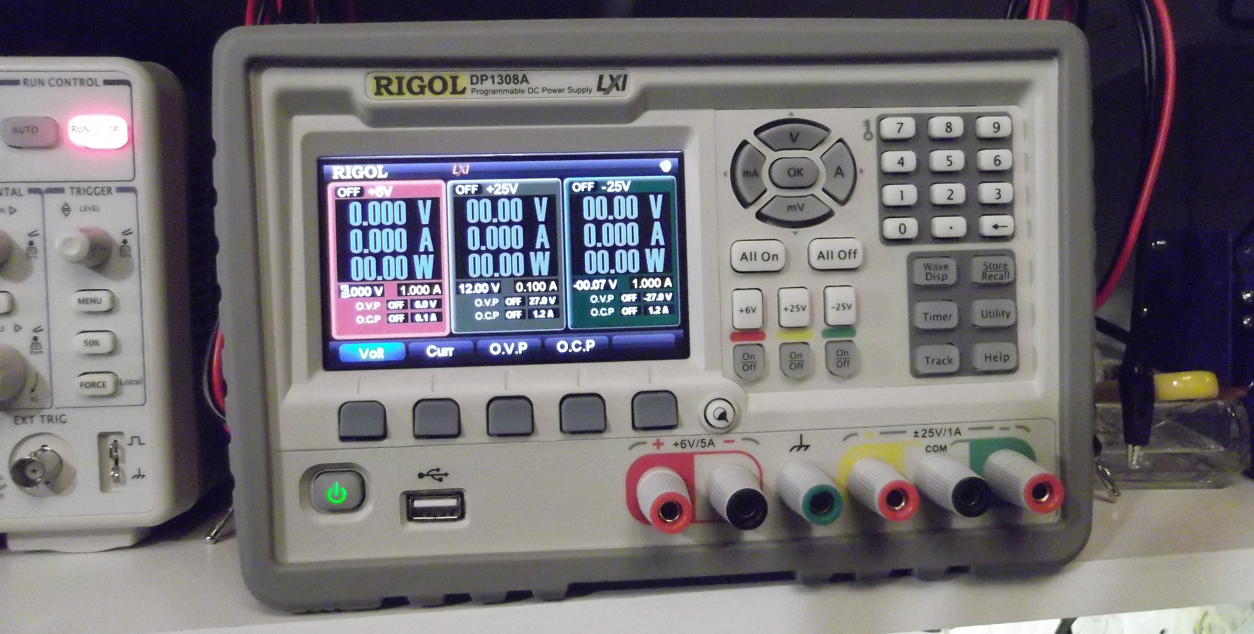
Set the desired voltage and the system will display the set point, and the voltage as measured at its outputs. On the PS1308A, this is just a 2-wire approach, the PS1116 uses a 4-wire setup.
By default, the display shows all 3 outputs at once, but you can zoom/focus on just one. If I’m just using one output, then I’ll set it to just focus on that.
For a detailed review of these power supplies, see this series of posts from Shahriar at thesignalpath
I’ll see about posting some tests at a variety of loads… not sure when I’ll get to that.
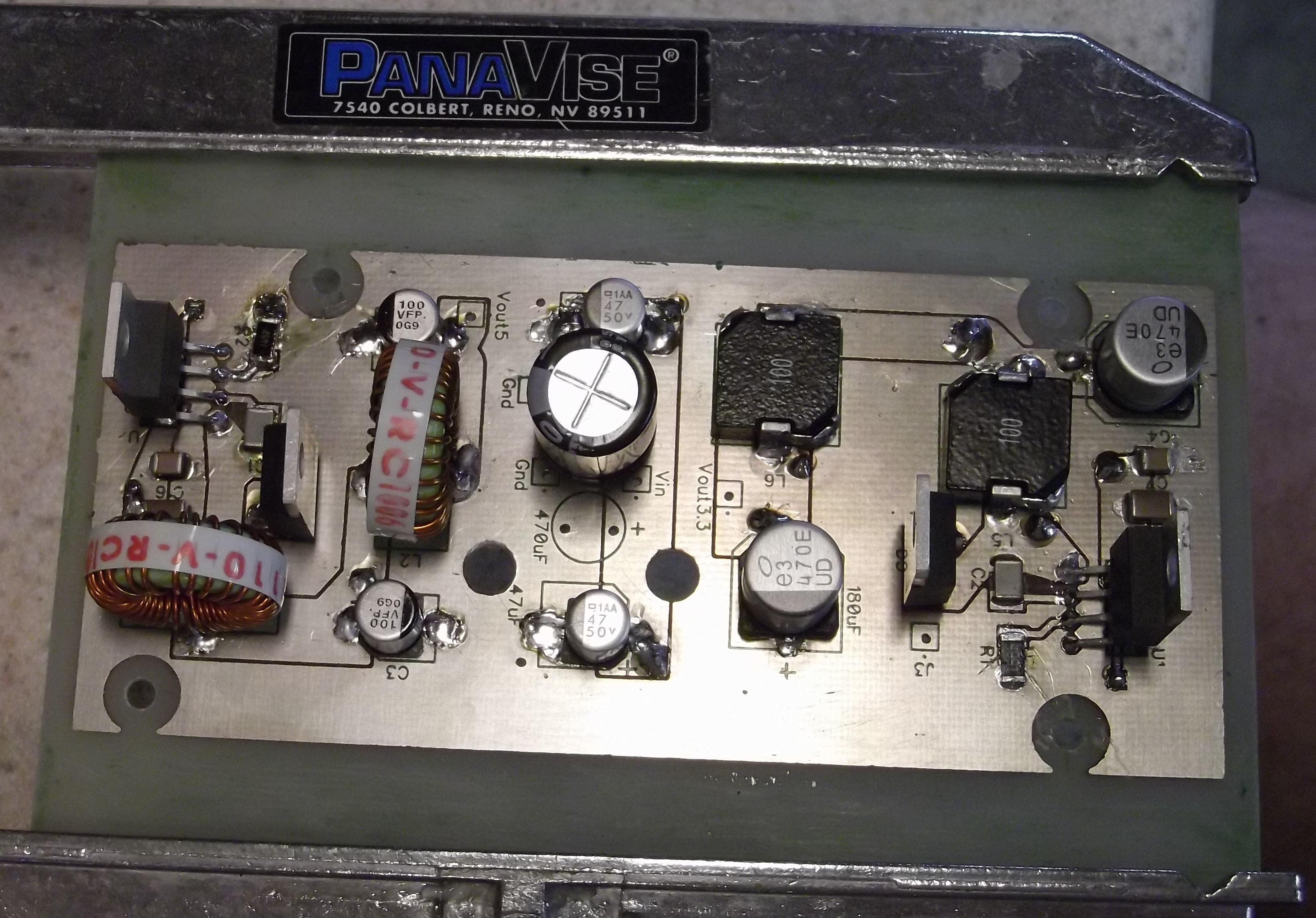
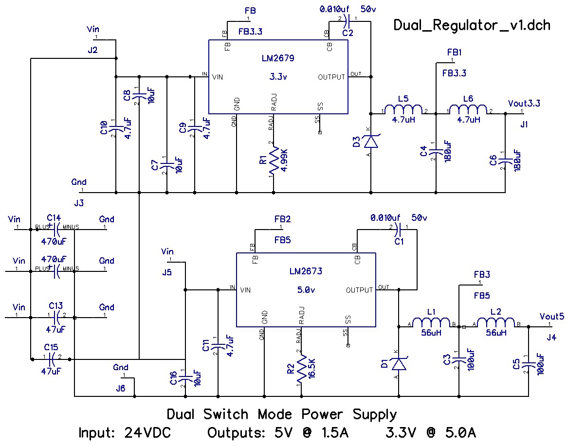
This is a dual output 5V and 3.3V power supply, that operates from a 12 – 24VDC input. The intended use is for powering a special networking switch from a batterybacked supply. The device will need to operate in amient outdoor temperatures in the the central plains.
Requirements:
Design is based upon the LM2673 5 volt and LM22679 3.3 Volt SMPS chips. These simplify the circuit and cut the number of external components required.
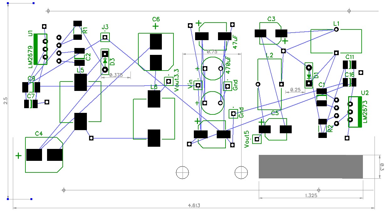
The circuit is very sensitive to layout. You can breadboard this, and it might run, but the output will be very noisy and may not deliver much current. This really does need careful layout on the PC board, with care to keep the boost capacitor close to the chip, and the diode close to the inductor.
 In the initial build, the 3.3V output has high noise (50mV p-p) and poor efficiency. Redesigned the layout and changed to a better diode: MBR745 from Vishay. The new layout only has 30mV peak-to-peak noise.
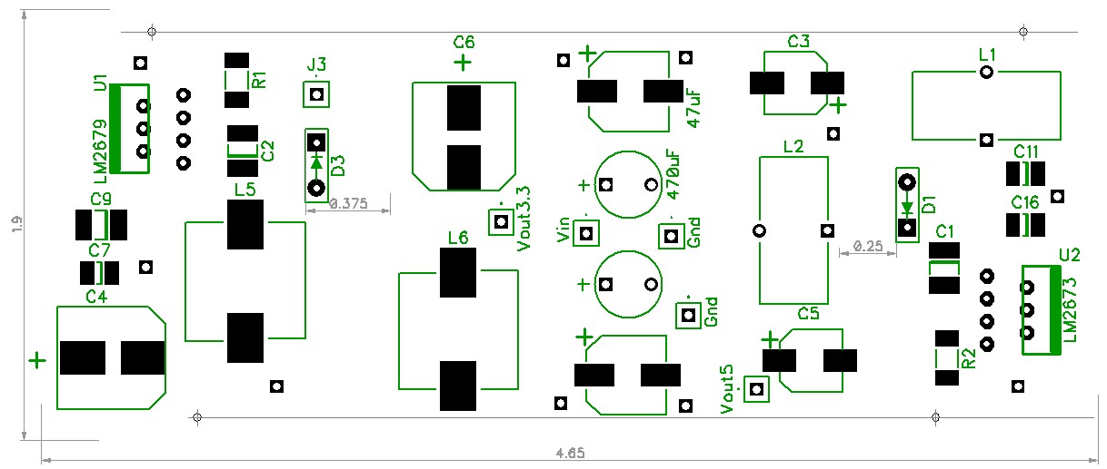
Shown here with out the copper pours, etc. The ICs and diodes are positioned with room to fit the heatsinks. This version runs the network switch quite well. The heatsinks do get warm, we’ll see how it performs outside on a hot day.
Received my µCurrent unit last week, and I finally got around to trying it out.
Nicely made, and performs exactly as described. But, since it’s from Dave Jones, that’s exactly what I expected.
Dave has provided lots of info about the µCurrent on his site, so I won’t go into the details. But, I did check the burden voltage:
| Range | Rating | Observed |
|---|---|---|
| 0 – 300mA | 70uV | 60uV |
| 0 – 1000uA | 10uV | 10uV |
| 0 – 1000nA | 10uV | 10uV |
Testing setup:
Procedure: setup for a particular current range, measure voltage with leads connected together(not through the µCurrent), then measure voltage with leads connected through the µCurrent.
Accuracy of µCurrent output:
Checked the accuracy of the current readings from the µCurrent output against the readings from my BK5491B. When using the EX505 to read the uCurrent output, the readings were ±1 of the last digit. When reading the voltage using the BK5491B, the µCurrent output was exactly correct.
