I need to determine whether a pump motor is running, and use that to trigger an ESP32. As luck would have it, the next day a colleague at work mentioned needing something similar for his home automation system. So, I created a video to describe the operation of the initial circuit that I created.
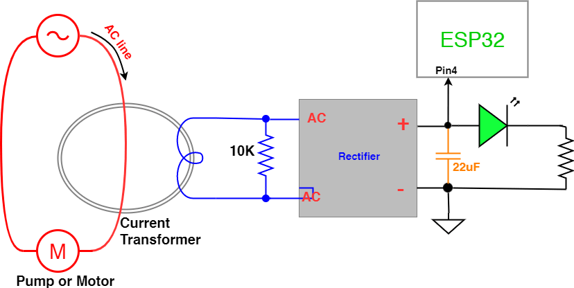
The current transformer shown is the CR8410-1000 from CR Magnetics.
Here’s the schematic:
This diagram includes the optional filter capacitor (inorange) shown in the video, this smooths out the waveform of the signal going into the ESP32.
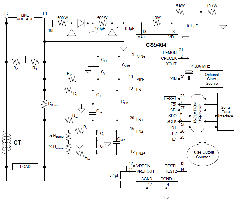
Continuing the series on examining devices to measure AC current, this time we’ll try out the CS5464 from Cirrus Logic. I initially built it up on a breadboard, but I’ll skip writing up this test and instead build up a prototype and run AC line power through it.
This is a Three-channel, Single-phase Power/Energy monitoring chip, and also can use current shunts and is intended for power meters.
This device provides no direct isolation, instead the entire device (input and output) directly coupled to the AC power line. Any isolation must be provided separately.
Taking a look at the project
Goals:
Monitor AC line voltage from 80 to 150 VAC RMS
check for low and high voltage conditions
stretch goal: identify short duration brown-outs and voltage spikes, the type caused by sudden switching of loads
Monitor AC current on 2 separate loads on the same AC circuit (phase)
Measure instantaneous current from 0 to 10 Amps, with 0.5 Amp accuracy
Detect low current and overcurrent conditions
Stretch goal: identify surges during load switching
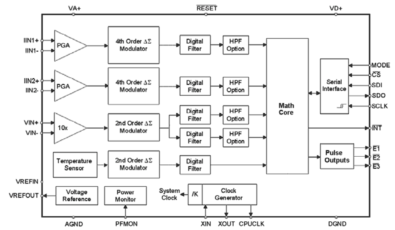
The CS5464 chip is really a standalone ASIC device that reads multiple ADC inputs and tracks the values on its own without external intervention.
It has a built-in voltage reference, and temperature sensor for automatic compensation.
It simultaneously tracks a variety of values for each channel, including:
Instantaneous Current
Instantaneous Voltage
Instantaneous Power
Active Power Channel
RMS Current Channel
RMS Voltage Channel
That’s just fantastic for my purposes!
This device should meet the goals of identifying brownouts, voltage spikes, and current surges without lots of reads or external processing. It should really lower the demands on the main microcontroller, allowing the core processor to focus on control and reporting functions… it should only need to ping the CS5464 occasionally to get the necessary data.
The CS5464 does indeed have a lot of functionality, but it also comes with a lot more complexity, it requires being reset properly after power-up and various configuration commands before you can get the data you’re after.
Cirrus application note
Prototyping with the CS5464 device can be quite simple, if you just want to simulate the AC power/current flowing through a small shunt using a function generator or other safe, low-voltage source.
But, if you want to use it safely with non-isolated AC line voltage, in a real-world situation, then it gets a little more complex.
To provide some margin of safety, I have separated the CS5464 measurement device from the microcontroller (here it’s an Arduino), using the ADuM41xx series galvanic digital isolators from Analog Devices.
But, the CS5464 and the “line side” of the couplers need power… This could be provided by a non-isolated capacitive drop approach, like this one in the application notes:
But, since I already have nice clean power for my microcontroller, I can just use a 5010 Iso-Power device. It’s small and needs few components.
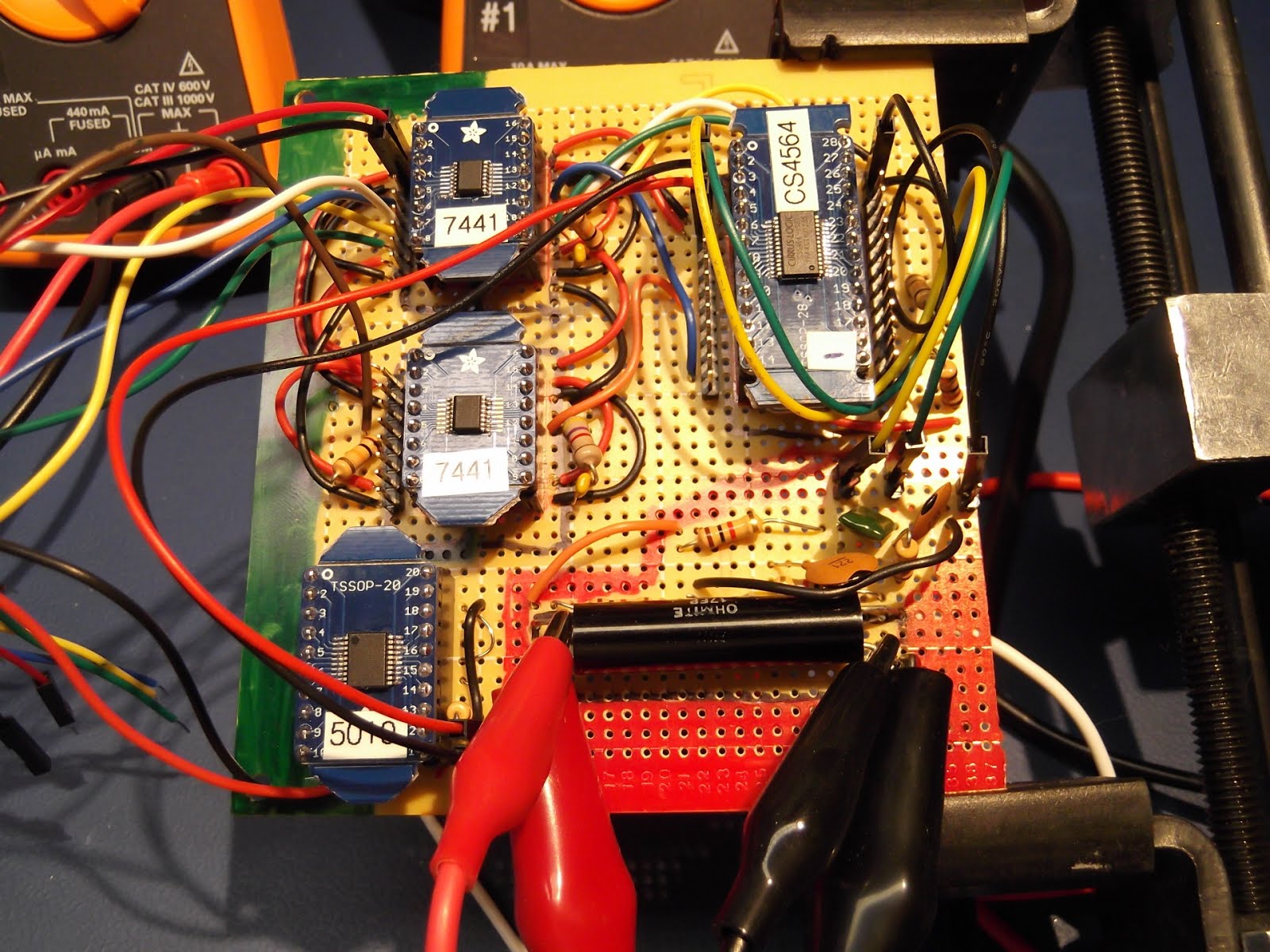
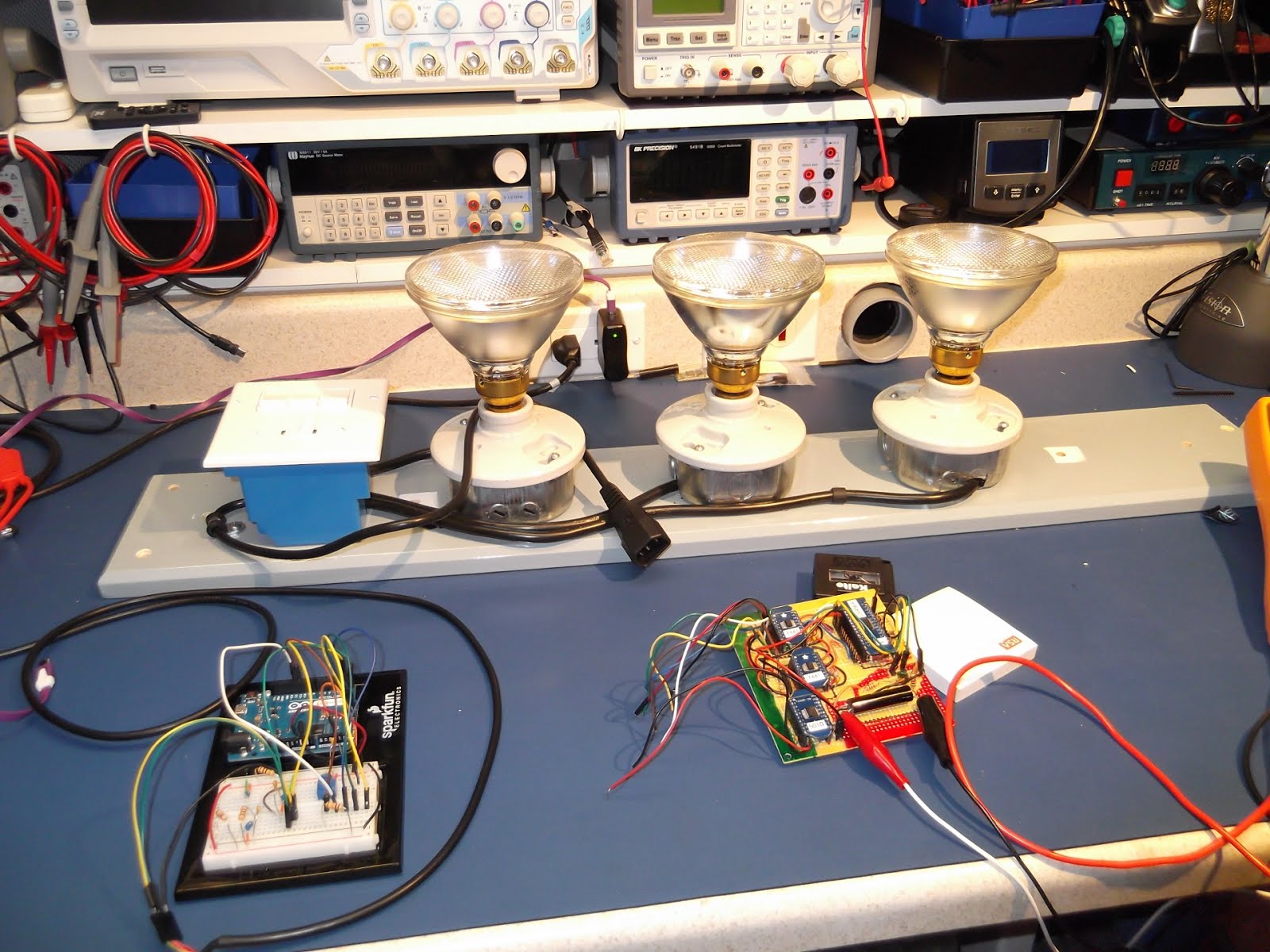
Here’s the test setup:
Even if I have to power all 8 channels on the ADum7441 devices, the total power will be 25ma, which should be okay for the IsoPower chip to run.
Here’s the prototype, built up on perfboard. Sections of the board are marked: Redis the AC input/shunt section Greenindicates the isolated, low voltage section that connects to the microcontroller
The unmarked area is logic-level signalling, but is tied directly to the AC line (no isolation)
Testing
I tested the prototype board measuring AC (line) current using a set of 150W lamps.
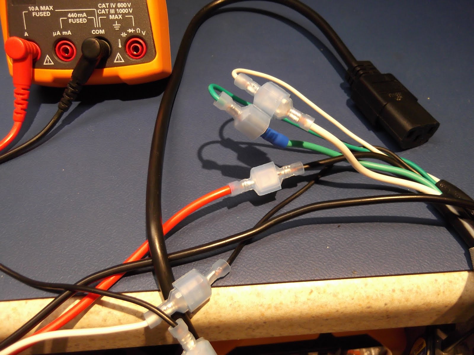
The test load is connected to the AC power and shunt via the IEC plug that is broken out to insulated spade connectors.
Test Results:
Input
(Amps)
Shunt Reading
(mV)
Counts
Counts, less
395 offset
Counts
per Amp
0
0.045
395
1.21
12.155
2444
2049
1693
2.41
24.152
4488
4093
1698
3.58
35.96
6500
6105
1705
The results are very linear, with only a little, steady increase in counts as the current rose. This could have been caused by thermal drift as the shunt warmed up under load.
Here’s some sample code for working with the CS5464. This code is not really my own, as much of it is a collection of snippets that I came across. I’ll see if I can find the original sources and reference those.
//  ** updated 6/26/2015 **
// This is written for an Arduino Leonardo.
// - it uses Serial1 instead of Serial, if you change it to Serial it should work for an UNO or other boards
//
// For CS5464 chip from Cirrus
// Read the peak current on channel I2
// Check for zero value coming back from CS5464, if so, then reset the device

#include <SPI.h>

// Pin configurations
// set pin 12 as the slave select for the digital pot:
const int slaveSelectPin = 12;

// set pin 11 as the Reset pin for the CS5464:
const int resetPin = 11;

// Create a data type for the 4 Byte data and command packet
union FourByte {
 struct {
 unsigned long value: 24; //24bit register values go in here
 byte command: 8; //8bit command goes in here.
 };
 byte bit8[4]; //this is just used for efficient conversion of the above into 4 bytes.
};

// Initialize SPI and pins
void setup() {
 // reset the CS5464 device
 pinMode(resetPin, OUTPUT);
 delay(100);
 digitalWrite(resetPin, LOW);
 delay(100);
 digitalWrite(resetPin, HIGH);
 delay(100);

 SPI.begin();
 SPI.setBitOrder(MSBFIRST);
 SPI.setDataMode(SPI_MODE3); //I believe it to be Mode3
 SPI.setClockDivider(SPI_CLOCK_DIV16);
 pinMode(slaveSelectPin, OUTPUT); // Do this manually, as the SPI library doesn't work right for all versions.
 digitalWrite(slaveSelectPin, HIGH);

 Serial1.begin(9600);
 delay(5000); // Pause allowing time to open the serial monitor
 Serial1.println("setup...");

 //Perform software reset:
 SPI_writeCommand(0x80);
 delay(2000);
 unsigned long status;
 do {
 status = SPI_read(0b00011110); //read the status register
 status &= (1UL << 23);
 } while (!status);

 // SPI_writeCommand(0xE0); //Set single conversion mode
 SPI_writeCommand(0xE8); //Set continuous conversion mode
/*
 // Print the configuration register, to confirm communication with the CS5464
 check = SPI_read(0x00); //read the config register.
 Serial1.print("Config = ");
 Serial1.println(check, HEX);
*/
 /*
 //example of writing a register
 union FourByte data;
 data.command = 0b01000000; //Write to config register
 data.value = 1; //This is the default value from datasheet, just using it as an example.
 SPI_writeRegister(data);
 */
}

// Main loop
void loop() {
 delay(1000);
 //example of reading data
 // unsigned long voltage = SPI_read(0b00001110); //read Register 7 Instantaneous Current Channel 2
 unsigned long voltage = SPI_read(0b00101100); //read Register 22 Peak Current Channel 2
 voltage = voltage >> 8;
 Serial1.print("Peak Current = ");
 Serial1.print(voltage, HEX);
 Serial1.print (" ");
 Serial1.println(voltage);

 // check if the device has accidentally reset
 // Found that noise from switching AC loads can cause the CS5464 to lock-up.
 // need to improve power or signal filtering, but this is a patch for initial testing.
 if (voltage == 0) { // If we get a 0 reading, then reconfigure the device
 SPI_writeCommand(0xE8); //Set continuous conversion mode
 delay(1000);
 unsigned long check = SPI_read(0x00); //read the config register.
 Serial1.print("Config = ");
 Serial1.println(check, HEX);
 }
}

// Send a Command to the CS5464 - see the data sheet for commands
void SPI_writeCommand(byte command) {
 digitalWrite(slaveSelectPin, LOW); //SS goes low to mark start of transmission
 union FourByte data = {0xFEFEFE, command}; //generate the data to be sent, i.e. your command plus the Sync bytes.
 Serial.print("SPI_writeCommand:");
 for (char i = 3; i >= 0; i--) {
 SPI.transfer(data.bit8[i]); //transfer all 4 bytes of data - command first, then Big Endian transfer of the 24bit value.
 Serial.print(data.bit8[i], HEX);
 }
 Serial.println();
 digitalWrite(slaveSelectPin, HIGH);
}

// Read a register from the CS5464 - just supply a command byte (see the datasheet)
unsigned long SPI_read(byte command) {
 digitalWrite(slaveSelectPin, LOW); //SS goes low to mark start of transmission
 union FourByte data = {0xFEFEFE, command}; //generate the data to be sent, i.e. your command plus the Sync bytes.
 // Serial.print("SPI_Read:");
 for (char i = 3; i >= 0; i--) {
 data.bit8[i] = SPI.transfer(data.bit8[i]); //send the data whilst reading in the result
 // Serial.print(data.bit8[i], HEX);
 }
 // Serial.println();
 digitalWrite(slaveSelectPin, HIGH); //SS goes high to mark end of transmission
 return data.value; //return the 24bit value recieved.
}
Like many hobbyists, I have a project where I need to measure AC line voltage and a couple of loads.
I started out trying to avoid doing anything complicated for power measurement… but I soon hit issues and the simple approach became increasingly more complicated, less accurate, and less reliable.
So, it’s time to reset that part of the project and evaluate a few approaches.
Goals:
Monitor AC line voltage from 80 to 150 VAC RMS
check for low and high voltage conditions
stretch goal: identify short duration brown-outs and voltage spikes, the type caused by sudden switching of loads
Monitor AC current on 2 separate loads on the same AC circuit (phase)
Measure instantaneous current from 0 to 10 Amps, with 0.5 Amp accuracy
Detect low current and overcurrent conditions
Stretch goal: identify surges during load switching
Constraints…
Size, I have some flexibility but an initial goal is to have the power and logic boards fit into a 4” x 8” space.
Standard U.S. single phase AC power
will be installed outdoors in an IP-67 enclosure
I have some aversion to messing with AC line voltage, and generally I work with little more than TTL levels. So, I opted for an isolated approach, that is: the AC line voltages are completely separated from the microcontroller and other logic.
This will allow me to have the AC sensing circuitry on a separate board allowing me to poke and prod the microcontroller without concern of any shock hazard.
Here’s a typical setup for the hall-effect sensor, and here’s a breakout board mounted in an enclosure to make using it on the bench with AC line voltage a bit safer.
{insert picture of ACS756 breakout}
I initially tested it out using a heavy DC power supply and load… it worked fine, was moderately accurate, and simple.
Results:
usable, but not great…
Test Results:
{ put in table here }
For AC current tests the system configuration is
Test Results:
… the results were a mess… random numbers all over the place!
Why?
When no current is flowing through the ACS756, the output is about 2.5V.
When we run positive current (the + output of the line is connected to the + on the ACS756), the output of the sensor goes up.
If we run negative current (the – output of the line is connected to the + on the ACS756), the output of the sensor goes down.
In this test we ran alternating current through the device, causing the ACS756 to provide a sine wave like output.
The readings were somewhat random, as it depended on where in the wave the Arduino took the sample.
{ put in table here }
I did try using a peak detector circuit. That helped, but the results were non-linear and it was really going to complicate things.
The control board design is complete, ready to etch it and see if it works… With 127 components (352 connections) there’s probably a Vdd or Gnd trace missing somewhere.
And the top and bottom layouts, without the copper pours. To control noise on the digital lines, the bottom layer will be as continuous a copper pour as possible.
Here’s the main controller, on the breadboard, and the readings from the Vref and SPI ADC.
Uses a PIC18F26K22 as the main controller, reads settings from BCD switches and controls SSD relays via a pair of MCP23S08 SPI chips, beacon and marker lamp currents are measured using 50 Amp ACD756 hall-effect sensors, their output is digitized using an MCP3004 ADC set to take differential readings.
As I continue to use the Microchip C18 compiler I find more and more issues. Microchip’s idiots appear to have left the peripherals lib out of the linker for the PIC18F2x/45K50 chips.
After changing over to use the K22 series of microcontrollers (specifically the PIC18F26K22), I found that the SPI libraries are missing from the linker. The USART libraries are there, but not the SPI.
Programs using SPI compile just fine, but won’t link…
Keep it up Microchip, and you may yet convince everyone to use Atmel.
So, I switched to an older compiler, version 3.40, and it works fine.
Here’s the code:
/*

* Uses SPI to read an MCP3004, and writes the results to the serial port.

*/
Here’s a fancier version of the usual blink routine that also demonstrates the various options for setting the internal oscillator.
/*

* A more complicated Blink program for the PIC18F26K22

*

* Set the clock:

* 111 = HFINTOSC ? (16 MHz)

* 110 = HFINTOSC/2 ? (8 MHz)

* 101 = HFINTOSC/4 ? (4 MHz)

* 100 = HFINTOSC/8 ? (2 MHz)

* 011 = HFINTOSC/16 ? (1 MHz)(3)

*

* Use the PLL to quadruple the frequency.

* OSCTUNEbits.PLLEN = 1;

*

* connect LEDs to RA0 - RA5

*

* The program clock speed can be measured on pin RA6

*/

#include /* MCU header file ***********/

#include
#pragma config WDTEN = OFF
#pragma config FOSC=INTIO7 // ;Internal oscillator block
#pragma config PLLCFG = ON
#pragma config PRICLKEN = ON
#pragma config IESO = OFF
#pragma config PWRTEN = OFF // ;Power up timer disabled
int counter;
void main (void)
{
OSCCON = 0x62; // Fosc = 8MHz
OSCCONbits.SCS0 = 0;
OSCCONbits.SCS1 = 0;
OSCTUNEbits.PLLEN = 1; // Use the PLL to up the clock to 32Mhz
counter = 1;
TRISA = 0; /* configure PORTB for output */
while (counter <= 255)
{
PORTA = counter; /* display value of ‘counter’ on the LEDs */
Delay10KTCYx(100);
counter++;
}
After having compiler issues using the new PIC18F25K50 chip, I switched to the K22 series. Specifically the 28 pin PIC18F26K22. The dual USART, dual SPI/I2C interfaces will be handy and allow for more flexible board layouts.
But, I had some difficulty getting the serial output to work. I read through a variety of examples, and questions/problems posted by others, most without responses. I did find several examples, but none of these worked. With some additional messing about, I managed to come up with this minimal Hello World example.
Hopefully the following will save someone else some time.
/* Serial Hello World

* This works!

* Clock set to 4Mhz, no PLL, transmits at 2400 Baud

* PIC18F26K22

* Complier: C18 v 3.45

*/
I have been using HiTech-C with great success on the PIC16F series chips. So, when I moved to the 18F series, I tried to stick with it. But, I hit a few problems…
The new PIC18F25K50 chips aren’t supported at all.
So, I tried the supported PIC18F26K22… Some things do work, but the string libraries don’t seem to work… so, might as well just ditch this, as the PIC18 version of the compiler hasn’t been updated for a long time, I expect that Microchip may be abandoning this in favor of their new C18 compiler.
After using the 16F series and some of the simpler 18F devices, I picked up some of the PIC18F25K50 microcontrollers.
I found that the HiTech-C compiler doesn’t support the K50 series at all, so I switched over to the C18 compiler. I can get the code to compile in C18, but it won’t link. It turns out that Microchip messedup the toolchain and didn’t include the necessary libs in version 3.45.
The only thing to do is pack up those chips and wait another 6–18 months for Microchip to pull their thumb out.


")


