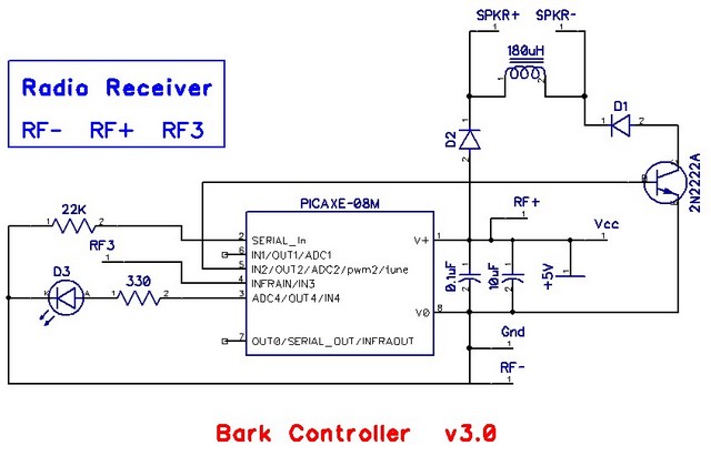
Category Archives: projects

Bark Controller

Device to discourage dogs from barking

Vision:

One or more remote controlled devices(annunciators) which will emit a high frequency audio pulse.  One or more remote transmitters that can trigger all remote annunciators simultaneously.


Principle of operation:

  1. Transmitters will use the 315MHz ISM band.  The transmitters will all use the same address/code.  Matching ISM receivers, all set to the same address/code.
  2. The audio frequency is not critical, and will sweep across a range of 18 – 22 KHz.  
  3. The audio will be generated by a PWM from a microcontroller.  
  4. The audio burst should be 3-5 seconds in duration.
  5. The PWM signal from the microcontroller will be sent through a 2N2222A to a piezo speaker with a parallel inductor to boost the voltage.
  6. The device should be able to run on 5 VDC.
  7. The device does not need to be battery powered, so standby power consumption is not critical.


Components:

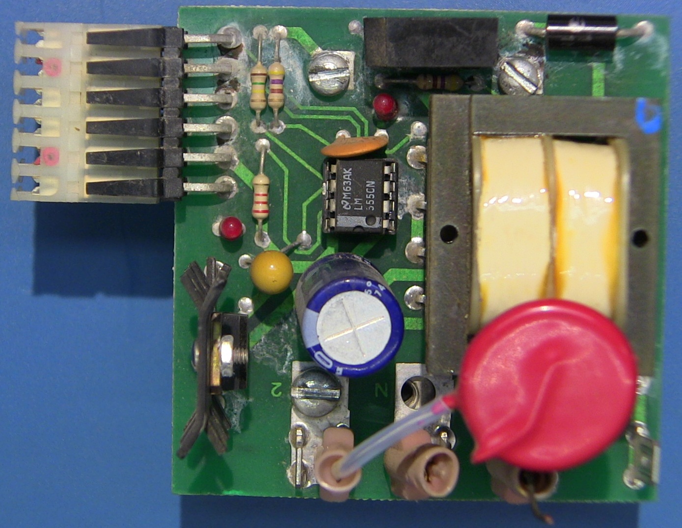
  • RF remote transmitter:  keyfob remote from Adafruit.com – based on the PT2262
  • RF receiver:  Simple RF T4 momentary from adafruit.com – based on the PT2272
  • Picaxe-08M2  – why?  had one laying around
  • Speaker:  piezo tweeter
  • Power Supply – 5V USB plug-in
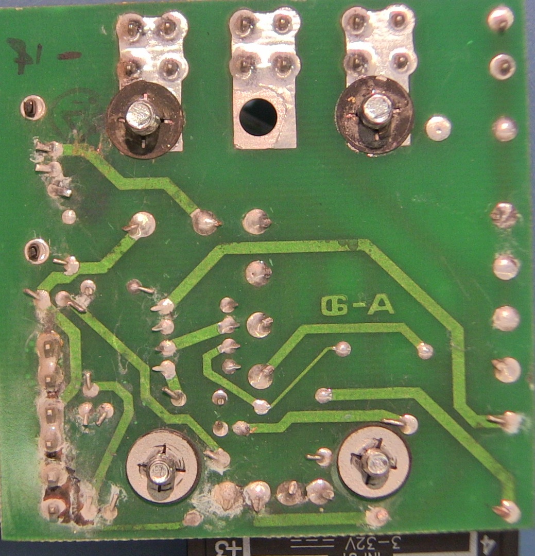
Circuit:

Bark_schm_f

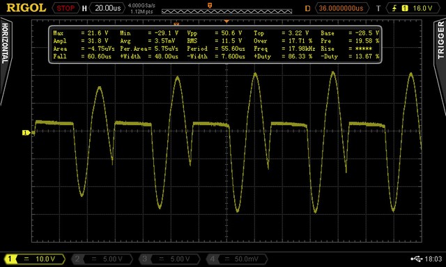
Screenshot of output, note the 50Vpp output:

Bark_scope1Here’s the code:

; Bark Controller
;  initializes LED and Piezo to OFF
;  waits for a signal
;   when a signal is received:
;   turn on LED
;   step through a set of 3 tones, 10 times
;   turn off the LED
;   turn off the sound
;   wait a couple of seconds
;
; Tones to play:
;   frequency 18Khz = pwmout C.2, 55, 111
;   frequency 20Khz = pwmout C.2, 49, 100
;   frequency 22Khz = pwmout C.2, 44, 91

low C.4 ;LED is C.3 = PIN 2
pwmout C.2, off  ;Piezo is C.2 = PIN 5
do  ;input is C.3 = PIN 4

if pin3 = 1 then
 high C.4 ;LED on
  For b0 = 1 to 10
pwmout C.2, 55, 111 ; 18Khz
pause 100  ; play for 0.1 seconds
pwmout C.2, 49, 100 ; 20Khz
pause 100
pwmout C.2, 44, 91 ; 22Khz
pause 100
  next
 low C.4
 pwmout C.2, off  ; turn off the piezo
 pause 2000
endif

loop


Radio Tower Navigation Lights

Yesterday, I received a small box of junk in priority mail.

Nav_parts Nav_box1

The lights weren’t working on a 400 ft. radio tower.  The controller’s enclosure was damaged and water had gotten in. 

The board had a fair amount of corrosion, and also some scorch marks. 

Nav_board_top1  Nav_board_bottom

It looks like there may have been some transients from lightning, as the leads to one of the MOVs has melted.

Nav_burn1 Nav_mov1

I toned out the connections, and it matches the typical NE555 oscillation circuit.  The damage was mostly limited to the MOVs (150L20), and the TVS protection diode (1N6281C).  But, before the TVS blew, it took out a couple of traces on the board.  So,I just bodged in a couple of wires to repair the trace, and it’s all running again.

DC-DC dual output Switch Mode Power Supply (SMPS)

Dual_SMPS_assembled

This is a dual output 5V and 3.3V power supply, that operates from a 12 – 24VDC input. The intended use is for powering a special networking switch from a batterybacked supply. The device will need to operate in amient outdoor temperatures in the the central plains.
Requirements:

  • Input:  10.8 –  26 VDC, with +/–  2V fluctuation
  • Output 1: 5VDC at 1.5 amps
  • Output 2: 3.3VDC at 5.0 amps
  • Output ripple < 40mv p-p
  • Temperature operating range (-40 to +60 degrees C.)
  • High efficiency

Design is based upon the LM2673 5 volt and LM22679 3.3 Volt SMPS chips.  These simplify the circuit and cut the number of external components required.

The circuit is very sensitive to layout.  You can breadboard this, and it might run, but the output will be very noisy and may not deliver much current.  This really does need careful layout on the PC board, with care to keep the boost capacitor close to the chip, and the diode close to the inductor.

Dual_regulator_v1In the initial build, the 3.3V output has high noise (50mV p-p) and poor efficiency.  Redesigned the layout and changed to a better diode:  MBR745 from Vishay.  The new layout only has 30mV peak-to-peak noise.

Dual_regulator_layout

Shown here with out the copper pours, etc. The ICs and diodes are positioned with room to fit the heatsinks.  This version runs the network switch quite well.  The heatsinks do get warm, we’ll see how it performs outside on a hot day.


Isolated USB ports

Problem:
Multiple bench meters, scopes, etc. that connect to a workstation through a USB hub.  Not all of the bench devices are optically isolated from the USB bus, so it is possible to get undesirable (and possibly damaging) ground loops through the equipment.

Solution:
While there are commercial USB hubs that provide isolation, they are rather expensive… typically starting around $350 for only a few ports.  It seems that one should be able to build something like this for much less.

One might think that it’s just a matter of splicing a couple of opto-isolators into the data wires, it’s much more complex, as shown here.
There are some useful chips on the market with fairly simple application notes.
This design will be based on the Analog Devices iCoupler ADuM3160 that supports both high and low speed USB, it may also supply peripheral power using an ACuM5000 chip.
We’ll keep the initial version simple and skip the common-mode chokes, and leave out any diode networks for ESD protection.
 
Based on this chipset, I should be able to provide isolated USB ports for $10 –  $15 per port.
 
Digikey has shipped the parts, now to design the board!
more to follow…
 
Recent Entries »