Like many hobbyists, I have a project where I need to measure AC line voltage and a couple of loads.
I started out trying to avoid doing anything complicated for power measurement… but I soon hit issues and the simple approach became increasingly more complicated, less accurate, and less reliable.
So, it’s time to reset that part of the project and evaluate a few approaches.
Goals:
- Monitor AC line voltage from 80 to 150 VAC RMS
- check for low and high voltage conditions
- stretch goal: identify short duration brown-outs and voltage spikes, the type caused by sudden switching of loads
Monitor AC current on 2 separate loads on the same AC circuit (phase)
- Measure instantaneous current from 0 to 10 Amps, with 0.5 Amp accuracy
- Detect low current and overcurrent conditions
- Stretch goal: identify surges during load switching
Constraints…
- Size, I have some flexibility but an initial goal is to have the power and logic boards fit into a 4” x 8” space.
- Standard U.S. single phase AC power
- will be installed outdoors in an IP-67 enclosure
I have some aversion to messing with AC line voltage, and generally I work with little more than TTL levels. So, I opted for an isolated approach, that is: the AC line voltages are completely separated from the microcontroller and other logic.
This will allow me to have the AC sensing circuitry on a separate board allowing me to poke and prod the microcontroller without concern of any shock hazard.
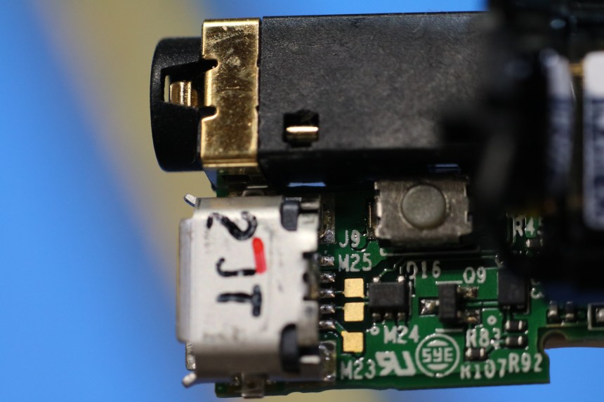
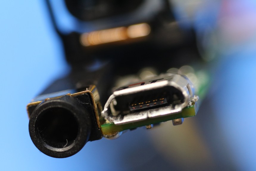
Here’s a typical setup for the hall-effect sensor, and here’s a breakout board mounted in an enclosure to make using it on the bench with AC line voltage a bit safer.
{insert picture of ACS756 breakout}
I initially tested it out using a heavy DC power supply and load… it worked fine, was moderately accurate, and simple.
")
Results:
usable, but not great…
Test Results:
{ put in table here }
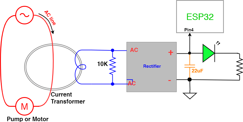
For AC current tests the system configuration is

Test Results:
… the results were a mess… random numbers all over the place!
Why?
- When no current is flowing through the ACS756, the output is about 2.5V.
- When we run positive current (the + output of the line is connected to the + on the ACS756), the output of the sensor goes up.
- If we run negative current (the – output of the line is connected to the + on the ACS756), the output of the sensor goes down.
In this test we ran alternating current through the device, causing the ACS756 to provide a sine wave like output.
The readings were somewhat random, as it depended on where in the wave the Arduino took the sample.
{ put in table here }
I did try using a peak detector circuit. That helped, but the results were non-linear and it was really going to complicate things.
The circuit was based upon the last one Dave Jones explains in EEVblog #490 at the 17:23
Here’s the code for the tests.
The basic test is just reading an analog input and printing the results to the serial port:
int analogPin = 3; // Connect output of ACS756 to analog pin 3
 // outside leads to ground and +5V
int val = 0; // variable to store the value read
void setup()
{
 Serial1.begin(9600); // setup serial
 pinMode(13, OUTPUT);
 digitalWrite(2, HIGH);
}
void loop()
{
 delay(495);
 digitalWrite(13, !digitalRead(13));
 val = analogRead(analogPin); // read the input pin
 Serial1.println(val); // debug value
}
The second test takes a large sample of readings and selects the largest value before printing the results to the serial port:
int analogPin = 3; // potentiometer wiper (middle terminal) connected to analog pin 3
 // outside leads to ground and +5V
int reading = 0; // variable to store the value read
long maxVal = 0;
int samples = 10000; // how many samples per reading

void setup()
{
 Serial1.begin(9600); // setup serial
 pinMode(13, OUTPUT);
 digitalWrite(2, HIGH);
}

void loop()
{
 maxVal = 0;
// delay(500);
// digitalWrite(13, !digitalRead(13));
 for (int counter = 1; counter < samples; counter++) {
 reading = analogRead(analogPin); // read the input pin
 if (reading > maxVal)
 {
 maxVal = reading;
 }
 }

 Serial1.println(maxVal); // debug value
}


")


