So, how do you know if your multimeter is giving you the right readings? The readings might have been correct (within spec) when it was new, but what about 6 months, or 20 years later? There are a plenty of expensive devices (not to mention calibration services) on the market to check equipment, but what about low-cost/hobbyist level?
Here are a few options from 2 sources:
Source: VoltageStandard.com
has several options, a couple of these are reviewed here:
DMM-Check $35.50 http://www.voltagestandard.com/DMMCheck.html
PentaRef $56.00 http://www.voltagestandard.com/PentaRef.html
Source: GellerLabs.com
Geller has two units, the one reviewed here is the SVR and it is readily available. The other unit, LNVR, is significantly more expensive and is more of a special order item.
SVR http://www.gellerlabs.com/SVR%20Series.htm $39.95
LNVR http://www.gellerlabs.com/LNVR%20Series.htm – special order
A month ago I had tested all three references and they appeared to be very accurate. I received a new, calibrated, Agilent 34410A DMM and decided to retest the references. The SVR and the DMM-Check both appeared to have remained accurate, but the Penta-Ref was a different story.
The Penta-Ref had been quite accurate on 2/21/12, when I checked it with a borrowed calibrated Agilent 34401A. But, on 3/20 with a new 34410A it seemed off. The next day I thought about it and checked the two 9-volt batteries which power the Penta-ref… sure enough, they were running a bit low. With the Penta-ref switched on, the battery voltages were 8.92 and 8.97. I replaced them with brand new batteries (9.6volts) and re-ran the tests. That fixed it, the Penta-ref was back on track.
On a similar note, the Geller SVR provided a steady 10.0000 volts output using an input voltage as low as 10.945V.
| Geller SVR 23.5° C |
| Value |
34410A |
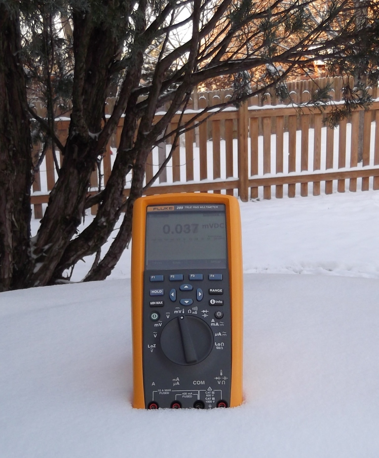
Fluke 289 |
| 10 Volts |
10.0000 |
10.000 |
| Penta-Ref |
|
New batteries 22° C |
Old batteries 23.5° C |
| Penta-ref Setting |
34410A |
Fluke 289 |
34410A |
Fluke 289 |
| 0.2500 |
0.25013 |
0.25013 |
0.25426 |
0.24543 |
| 0.4900 |
0.49007 |
0.49009 |
0.49821 |
0.4983 |
| 0.5100 |
0.51009 |
.51012 |
0.51855 |
0.5186 |
| 4.9000 |
4.9001 |
4.9004 |
4.9817 |
4.982 |
| 10.0000 |
10.0000 |
10.0001 |
10.1666 |
10.167 |
| DMM-Check 23.5° C |
| Value |
34410A |
Fluke 289 |
| 5 Volts |
5.0002 |
5.0006 |
| 1 mA |
0.99994 |
1.003 |
| 999.4Ω |
999.23k |
999.3k |
| 9.996kΩ |
9.9961k |
9.999k |
| 99.97kΩ |
99.976k |
99.99k |
– – UPDATE 4/2/12 – –
I was contacted by Doug Malone of VoltageStandard.com, he noticed this post and felt that the Penta-Ref should not experience a problem with the battery levels that I listed. He requested that I return it for adjustment/repair. So, I’ve sent it, and the DMM-Check to Doug for calibration. I’ll post new results when I get the units back from Doug.
That’s great customer service!
Also, it looks like there’s a new model coming, the DMM-Check Plus. It will include a 5VAC rms voltage reference, 1mA rms AC current reference, 100Hz precision frequency source, and 0.1%, 10ppm 100OHM precision resistor
– – UPDATE 4/10/12 – –
I mailed the units back USPS on the evening of 4/3, and received the recalibrated units on Monday 4/9, that was fast! I let them sit on the bench overnight to acclimatize before testing.
To test the drop-out voltage on the PentaRef, I temporarily replaced the batteries with 2 isolated bench power supplies. The PentaRef provided stable accurate output, identical to the battery readings (below) when run at voltages from 9.5V down to 6.5V. It did not matter if one supply was set at 6.5V and the other at 9.5V, the reference output remained the same.
Test setup:
- All tests were performed at 21° C.
- The Agilent 34410A was set to manual range for each test, with NPLC set to 10, and nulled.
- The Fluke 289 was also set to manual ranging and nulled for each test.
- One pair of Agilent probes was used for all tests, and was moved between meters for each set of tests.
- The PentaRef and DMM-Check units were powered by fairly new 9V batteries, providing 9.2V under load. The Geller SVR was powered by a Rigol 1308A set at 15.00 Volts.
| Geller SVR |
| Value |
34410A |
Fluke 289 |
notes |
| 10 Volts |
10.00005 |
10.001 |
within meter’s spec |
| Penta-Ref |
| Setting |
34410A |
Fluke 289 |
notes |
| 0.2500 |
0.250036 |
0.2500 |
well within device spec of 0.2% |
| 0.4900 |
0.489981 |
0.4900 |
well within device spec of 0.2% |
| 0.5100 |
0.509995 |
.5100 |
within meter’s spec |
| 4.9000 |
4.89989 |
4.9001 |
within meter’s spec |
| 10.0000 |
9.99986 |
10.000 |
within meter’s spec |
| DMM-Check |
| Value |
34410A |
Fluke 289 |
notes |
| 5 Volts |
4.99994 |
5.0001 |
well within device spec of 0.01% |
| 1 mA |
0.999923 |
1.000 |
well within device spec of 0.1% |
| 999.2Ω |
999.231Ω |
999.2Ω |
|
| 9.996kΩ |
9.99605k |
9.996k |
|
| 99.97kΩ |
99.9746k |
99.97k |
|
Summary
Based on the results above, all tests fall well within spec. The Agilent has exceptional accuracy and resolution, and may make it appear the the voltage references aren’t spot on. But, we have to account for the device’s rated accuracy, compounded by the accuracy of the meter. So, in these tests, “Within meter’s spec” means that he reading is so close to the specified voltage that I can’t tell if the generated voltage is precisely correct (Example: specified value is 0.5100 volts, I measured 0.509995 Volts. The meter’s accuracy for that reading is +/– 0.000016 volts, so the device may be producing exactly 0.510000 volts, but I can’t be sure).


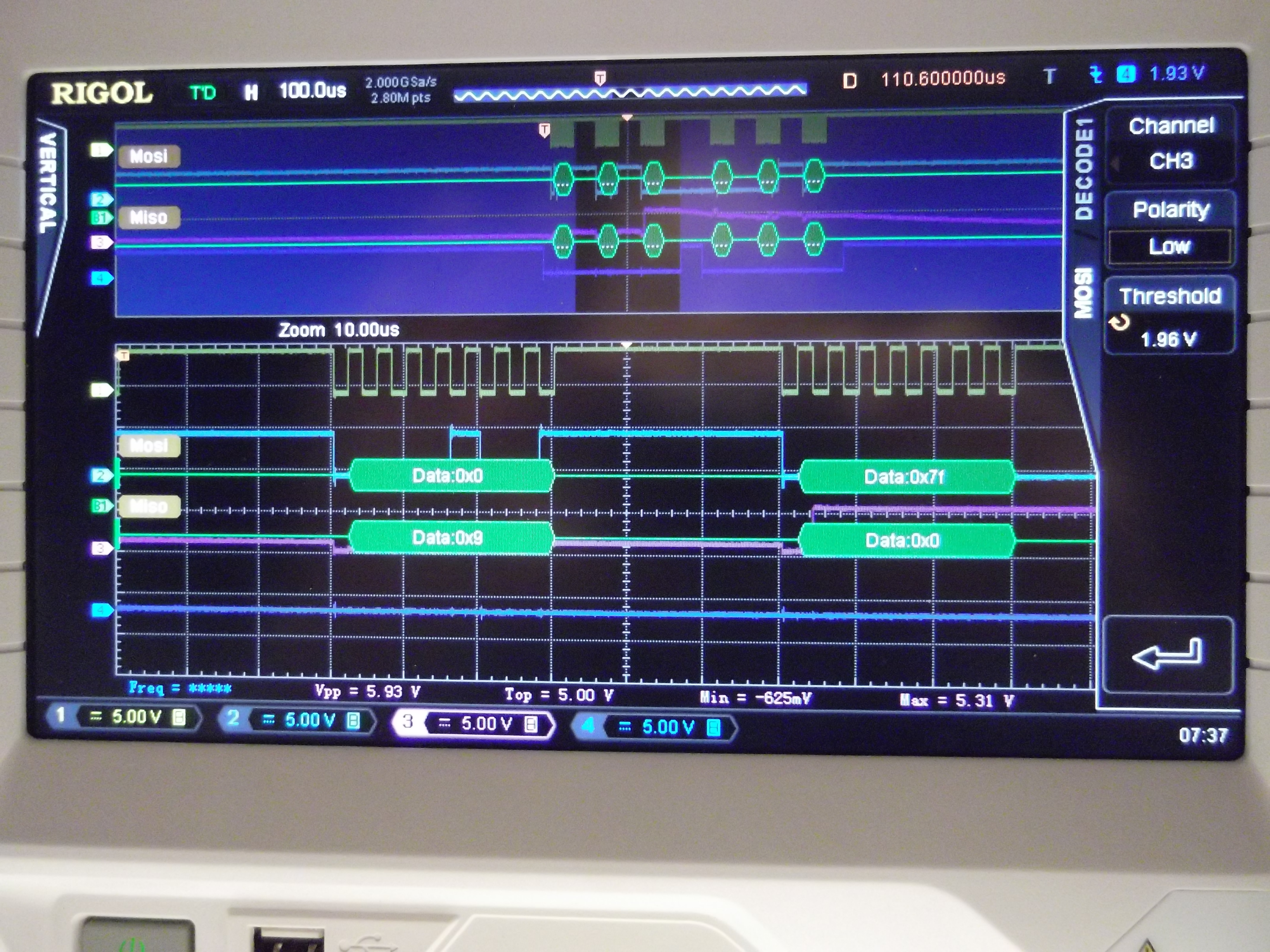
 Here’s the code: