Monthly Archives: February 2012

Rigol PS1308A – Triple Output Power Supply

Rigol_DP1308A
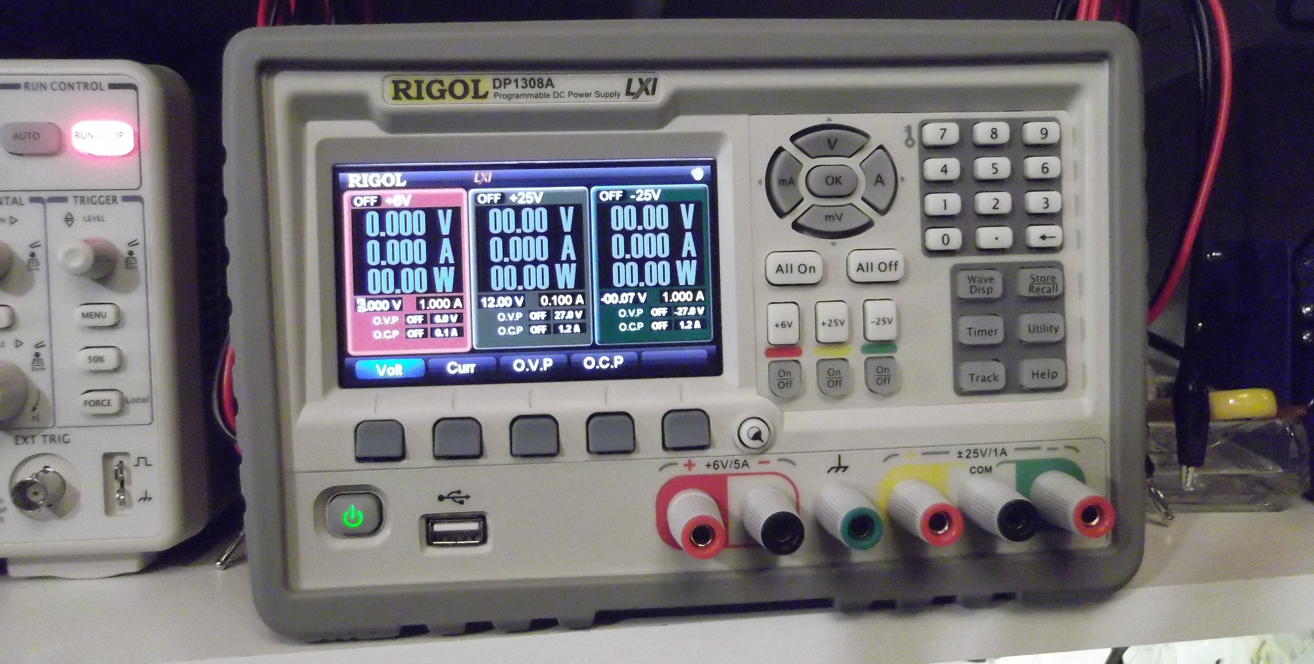
The Rigol PS1308A is a really nice unit.  Very stable, clean output.  Beautiful user interface, that’s simple and intuitive.  There’s even an ethernet connection with a web interface.  I haven’t tried out the USB connection with LabView yet.
Details:
  • 3 output, 80 watt PSU
  • 0 to +6 volts at 0-5 amps
  • 0 to +25 volts at 0-1 amp
  • 0 to -25 volts as 0-1 amp
  • individually switched outputs, and all on/off

Set the desired voltage and the system will display the set point, and the voltage as measured at its outputs.  On the PS1308A, this is just a 2-wire approach, the PS1116 uses a 4-wire setup.

By default, the display shows all 3 outputs at once, but you can zoom/focus on just one.  If I’m just using one output, then I’ll set it to just focus on that.

For a detailed review of these power supplies, see this series of posts from Shahriar at thesignalpath

I’ll see about posting some tests at a variety of loads… not sure when I’ll get to that.


DC-DC dual output Switch Mode Power Supply (SMPS)

Dual_SMPS_assembled

This is a dual output 5V and 3.3V power supply, that operates from a 12 – 24VDC input. The intended use is for powering a special networking switch from a batterybacked supply. The device will need to operate in amient outdoor temperatures in the the central plains.
Requirements:

  • Input:  10.8 –  26 VDC, with +/–  2V fluctuation
  • Output 1: 5VDC at 1.5 amps
  • Output 2: 3.3VDC at 5.0 amps
  • Output ripple < 40mv p-p
  • Temperature operating range (-40 to +60 degrees C.)
  • High efficiency

Design is based upon the LM2673 5 volt and LM22679 3.3 Volt SMPS chips.  These simplify the circuit and cut the number of external components required.

The circuit is very sensitive to layout.  You can breadboard this, and it might run, but the output will be very noisy and may not deliver much current.  This really does need careful layout on the PC board, with care to keep the boost capacitor close to the chip, and the diode close to the inductor.

Dual_regulator_v1In the initial build, the 3.3V output has high noise (50mV p-p) and poor efficiency.  Redesigned the layout and changed to a better diode:  MBR745 from Vishay.  The new layout only has 30mV peak-to-peak noise.

Dual_regulator_layout

Shown here with out the copper pours, etc. The ICs and diodes are positioned with room to fit the heatsinks.  This version runs the network switch quite well.  The heatsinks do get warm, we’ll see how it performs outside on a hot day.


Isolated USB ports

Problem:
Multiple bench meters, scopes, etc. that connect to a workstation through a USB hub.  Not all of the bench devices are optically isolated from the USB bus, so it is possible to get undesirable (and possibly damaging) ground loops through the equipment.

Solution:
While there are commercial USB hubs that provide isolation, they are rather expensive… typically starting around $350 for only a few ports.  It seems that one should be able to build something like this for much less.

One might think that it’s just a matter of splicing a couple of opto-isolators into the data wires, it’s much more complex, as shown here.
There are some useful chips on the market with fairly simple application notes.
This design will be based on the Analog Devices iCoupler ADuM3160 that supports both high and low speed USB, it may also supply peripheral power using an ACuM5000 chip.
We’ll keep the initial version simple and skip the common-mode chokes, and leave out any diode networks for ESD protection.
 
Based on this chipset, I should be able to provide isolated USB ports for $10 –  $15 per port.
 
Digikey has shipped the parts, now to design the board!
more to follow…
 

eevBlog µCurrent is here!

Received my µCurrent unit last week, and I finally got around to trying it out.

Nicely made, and performs exactly as described.  But, since it’s from Dave Jones, that’s exactly what I expected.

Dave has provided lots of info about the µCurrent on his site, so I won’t go into the details.  But, I did check the burden voltage:

Range Rating Observed
0 – 300mA 70uV 60uV
0 – 1000uA 10uV 10uV
0 – 1000nA 10uV 10uV

Testing setup:

  • 1.000 on Rigol DP1308A, run through a 1% resistor (different value for each range).
  • voltage drop using BK5491B (50,000 count) DMM.
  • output from µCurrent measured with EX505 (4,000 count) DMM.
  • Temperature 20°C

Procedure: setup for a particular current range, measure voltage with leads connected together(not through the µCurrent), then measure voltage with leads connected through the µCurrent.

Accuracy of µCurrent output:
Checked the accuracy of the current readings from the µCurrent output against the readings from my BK5491B. When using the EX505 to read the uCurrent output, the readings were ±1 of the last digit. When reading the voltage using the BK5491B, the µCurrent output was exactly correct.