Continuing the series on examining devices to measure AC current, this time we’ll try out the CS5464 from Cirrus Logic. I initially built it up on a breadboard, but I’ll
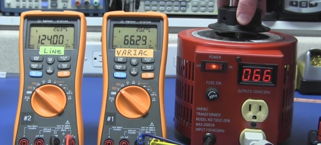
Adding a digital volt meter to a variac, adding a missing ground strap, and insulation testing of the chassis powder coat. The display I installed is available from MPJA.com Panel
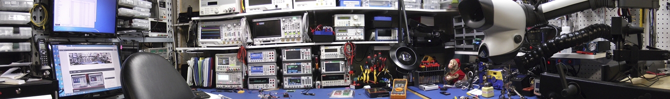
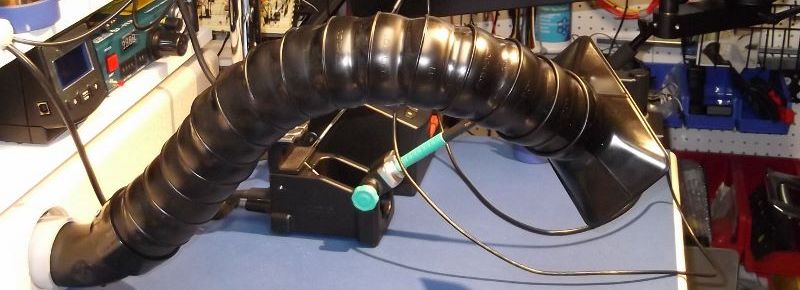
I’ve used the usual free-standing table top fume extractors, but they’re noisy and always seem to be in the way. So, when I was reconfiguring my bench, I built the
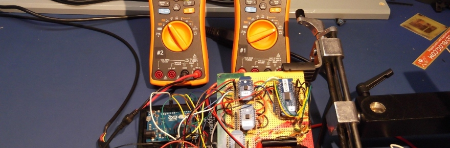
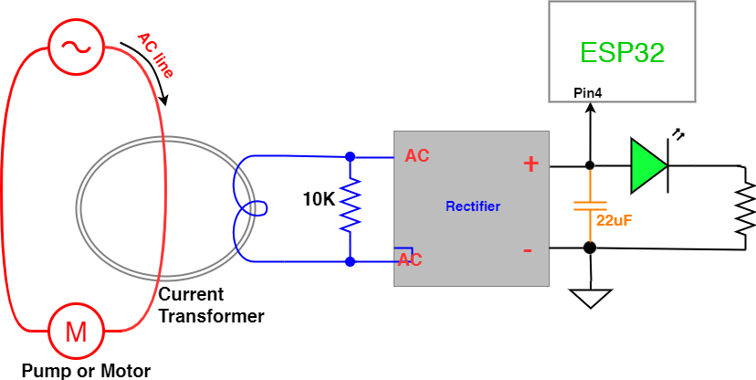
I need to determine whether a pump motor is running, and use that to trigger an ESP32. As luck would have it, the next day a colleague at work mentioned needing something similar for his home automation system. So, I created a video to describe the operation of the initial circuit that I created.
The current transformer shown is the CR8410-1000 from CR Magnetics.
Here’s the schematic:
This diagram includes the optional filter capacitor (inorange) shown in the video, this smooths out the waveform of the signal going into the ESP32.
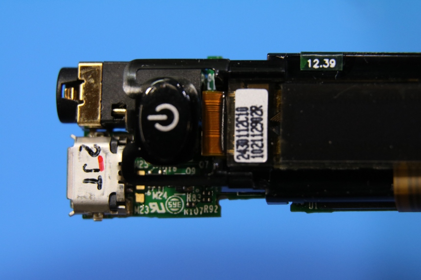
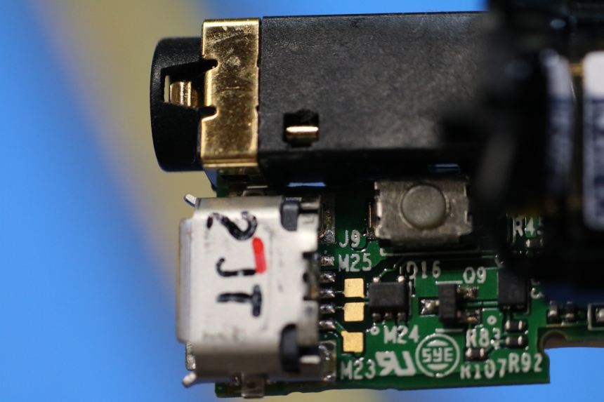
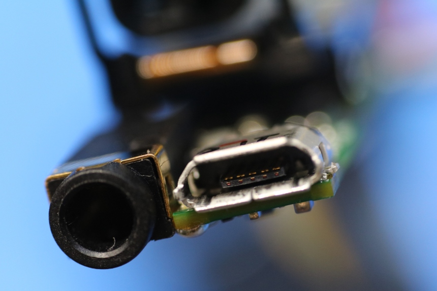
There have been a few questions posted on YouTube from viewers that have problems with a damaged or “pushed-in” USB connector on their Livescribe pens.
To assist them with what’s inside, here are a few close-up photos.
I hope the picures help those needing to fix the USB ports on their pens.
Like many hobbyists, I have a project where I need to measure AC line voltage and a couple of loads.
I started out trying to avoid doing anything complicated for power measurement… but I soon hit issues and the simple approach became increasingly more complicated, less accurate, and less reliable.
So, it’s time to reset that part of the project and evaluate a few approaches.
Goals:
Monitor AC line voltage from 80 to 150 VAC RMS
check for low and high voltage conditions
stretch goal: identify short duration brown-outs and voltage spikes, the type caused by sudden switching of loads
Monitor AC current on 2 separate loads on the same AC circuit (phase)
Measure instantaneous current from 0 to 10 Amps, with 0.5 Amp accuracy
Detect low current and overcurrent conditions
Stretch goal: identify surges during load switching
Constraints…
Size, I have some flexibility but an initial goal is to have the power and logic boards fit into a 4” x 8” space.
Standard U.S. single phase AC power
will be installed outdoors in an IP-67 enclosure
I have some aversion to messing with AC line voltage, and generally I work with little more than TTL levels. So, I opted for an isolated approach, that is: the AC line voltages are completely separated from the microcontroller and other logic.
This will allow me to have the AC sensing circuitry on a separate board allowing me to poke and prod the microcontroller without concern of any shock hazard.
Here’s a typical setup for the hall-effect sensor, and here’s a breakout board mounted in an enclosure to make using it on the bench with AC line voltage a bit safer.
{insert picture of ACS756 breakout}
I initially tested it out using a heavy DC power supply and load… it worked fine, was moderately accurate, and simple.
Results:
usable, but not great…
Test Results:
{ put in table here }
For AC current tests the system configuration is
Test Results:
… the results were a mess… random numbers all over the place!
Why?
When no current is flowing through the ACS756, the output is about 2.5V.
When we run positive current (the + output of the line is connected to the + on the ACS756), the output of the sensor goes up.
If we run negative current (the – output of the line is connected to the + on the ACS756), the output of the sensor goes down.
In this test we ran alternating current through the device, causing the ACS756 to provide a sine wave like output.
The readings were somewhat random, as it depended on where in the wave the Arduino took the sample.
{ put in table here }
I did try using a peak detector circuit. That helped, but the results were non-linear and it was really going to complicate things.
The control board design is complete, ready to etch it and see if it works… With 127 components (352 connections) there’s probably a Vdd or Gnd trace missing somewhere.
And the top and bottom layouts, without the copper pours. To control noise on the digital lines, the bottom layer will be as continuous a copper pour as possible.
New Mantis Compact inspection scope arrived, with articulated boom arm. The Mantis on the left with the standard binocular AmScope on the right.
This scope provides a great 3D view, without peering through little eye pieces. The Mantis provides a much sharper image than the Amscope’s optics. And you can shift sligtly while looking through the Mantis and change your perspective of the board, this is very handy for getting a better perspective when working on small devices.
The AmScope is still handy for high magnification (up to 200x), but most inspection work is in the 4x – 8x range, and the Mantis is great for that.
The optional articulating arm provides good reach across the workbench, and was a worthwhile option.
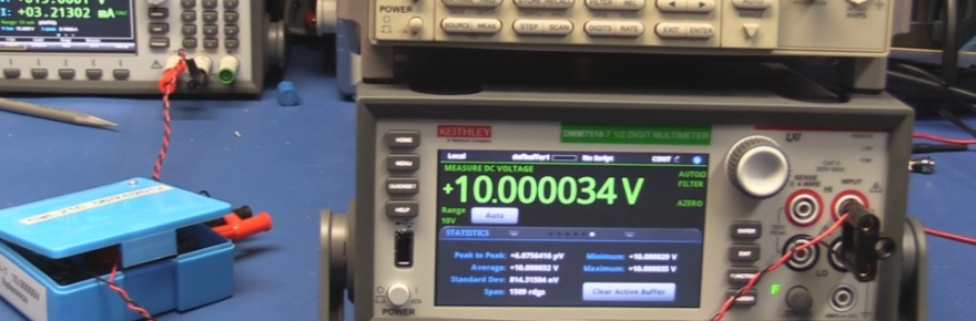
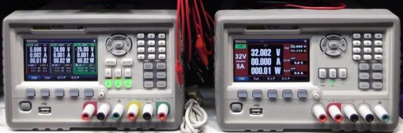
Here’s the main controller, on the breadboard, and the readings from the Vref and SPI ADC.
Uses a PIC18F26K22 as the main controller, reads settings from BCD switches and controls SSD relays via a pair of MCP23S08 SPI chips, beacon and marker lamp currents are measured using 50 Amp ACD756 hall-effect sensors, their output is digitized using an MCP3004 ADC set to take differential readings.
As I continue to use the Microchip C18 compiler I find more and more issues. Microchip’s idiots appear to have left the peripherals lib out of the linker for the PIC18F2x/45K50 chips.
After changing over to use the K22 series of microcontrollers (specifically the PIC18F26K22), I found that the SPI libraries are missing from the linker. The USART libraries are there, but not the SPI.
Programs using SPI compile just fine, but won’t link…
Keep it up Microchip, and you may yet convince everyone to use Atmel.
So, I switched to an older compiler, version 3.40, and it works fine.
Here’s the code:
/*

* Uses SPI to read an MCP3004, and writes the results to the serial port.

*/
Here’s a fancier version of the usual blink routine that also demonstrates the various options for setting the internal oscillator.
/*

* A more complicated Blink program for the PIC18F26K22

*

* Set the clock:

* 111 = HFINTOSC ? (16 MHz)

* 110 = HFINTOSC/2 ? (8 MHz)

* 101 = HFINTOSC/4 ? (4 MHz)

* 100 = HFINTOSC/8 ? (2 MHz)

* 011 = HFINTOSC/16 ? (1 MHz)(3)

*

* Use the PLL to quadruple the frequency.

* OSCTUNEbits.PLLEN = 1;

*

* connect LEDs to RA0 - RA5

*

* The program clock speed can be measured on pin RA6

*/

#include /* MCU header file ***********/

#include
#pragma config WDTEN = OFF
#pragma config FOSC=INTIO7 // ;Internal oscillator block
#pragma config PLLCFG = ON
#pragma config PRICLKEN = ON
#pragma config IESO = OFF
#pragma config PWRTEN = OFF // ;Power up timer disabled
int counter;
void main (void)
{
OSCCON = 0x62; // Fosc = 8MHz
OSCCONbits.SCS0 = 0;
OSCCONbits.SCS1 = 0;
OSCTUNEbits.PLLEN = 1; // Use the PLL to up the clock to 32Mhz
counter = 1;
TRISA = 0; /* configure PORTB for output */
while (counter <= 255)
{
PORTA = counter; /* display value of ‘counter’ on the LEDs */
Delay10KTCYx(100);
counter++;
}
After having compiler issues using the new PIC18F25K50 chip, I switched to the K22 series. Specifically the 28 pin PIC18F26K22. The dual USART, dual SPI/I2C interfaces will be handy and allow for more flexible board layouts.
But, I had some difficulty getting the serial output to work. I read through a variety of examples, and questions/problems posted by others, most without responses. I did find several examples, but none of these worked. With some additional messing about, I managed to come up with this minimal Hello World example.
Hopefully the following will save someone else some time.
/* Serial Hello World

* This works!

* Clock set to 4Mhz, no PLL, transmits at 2400 Baud

* PIC18F26K22

* Complier: C18 v 3.45

*/


")


